How to Calculate ARC Pulsation Parameters

Arc pulsing involves four welding parameters; Peak current, background current, pulse width (duty cycle or percent – on – time), and pulse frequency (pulses per second). Although the parameters are most often chosen and changed according to the specific needs there are some industry standards that have been developed as starting parameters. Experimentation and experience will determine the final weld parameters chosen.

Step One : Average Current Required : Using the power supply in the unpulsed mode, establish the weld current required to melt and fuse the materials to be welded. Some times this weld current can be calculated using the 1 amp per 0.001” of material thickness rule. Example: If the material thickness or depth of weld penetration is 0.060 then 60 amps of average weld current will be required. Continue to increase the weld speed and current until a point where the arc and weld are still giving consistent results.

Step Two : Peak and Background Current Settings : The average current will be effected both by the peak to background current ratios and the duty cycle/pulse width (the percentage of time spent on the peak current setting) As before, these settings are changed according to the specific needs of the application. Peak to background current are normally in ratios of 2 – 5 and pulse widths are often 20% to 50%

Step Three : Pulsation Rate : This is difficult to calculate with any accuracy. The best method is to actually incre ase and decrease the pulsation rates until the overlap of weld spots is between 50% to 90%

If necessary a ballpark starting value can be pre – calculated using the following formula:


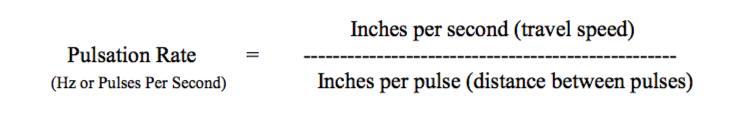
(Hz or Pulses Per Second) Inches per pulse (distance between pulses)

Example: Stainless steel material of thickness 0.060” being welded with a travel speed of 10 i nches per minute (0.16 inches per second) and a desired spot overlap of 75%. The weld puddle size will probably be 2.5 times the wall thickness (depending on any tooling used) so the distance between spot edges will be (2.5 x 0.06 x (1 – 0.75)) = 0.037


Many times, for thin wall or shallow penetration the starting pulsation rate will be half the travel speed in IPM. In the example above the travel speed was 10 IPM and the starting pulsation rate could be taken as 5 PPS

Varying the pulsation rate may also give a more stable arc for a given set of parameters and thus more consistent weld results. Experimentation and experience will determine the final weld parameters.

Process Welding Systems NEWSLETTER

 The Plasma and TIG welding Expert

Our expertise, through the years, has been in PAW (Plasma Arc Welding) and GTAW (Gas Tungsten Arc Welding). It has been our experience that very clean gas in low amp plasma arc welding is very important.

As a result, we have written a procedure for welders, to help find some of the problems that can be caused by moisture and oxygen getting into the gas lines during welding. Please note the Attached Procedure “Check List for Contaminated Electrode, Dirty Weld Nozzles and Plasma Torch Care.”

A wide variety of tungsten electrodes can be used during welding. Most welders prefer thoriated tungsten electrodes, but others like ceriated or lanthanated tungsten electrodes. It is difficult to determine which is best. The welder must consider his welding application, type of gas used, type of power supply, pulse rate, material being welded, etc. See the Attached Tungsten Sheet.

Please feel free to use the “Check List for Contaminated Electrode, Dirty Weld Nozzles and Plasma Torch Care” and the Tungsten Information Sheet. Pass them on to your welding engineers and welding technicians.

LOW AMP PLASMA WELDING

CHECK LIST FOR CONTAMINATED ELECTRODE, DIRTY WELD NOZZLES AND PLASMA TORCH CARE.

  1. A dark blue or black tungsten (Figure B) is a sign of moisture or oxygen getting into the plasma gas line (also called the pilot gas line). If the gas is good quality and the gas lines are leak free, the tungsten should remain a gray color (Figure A) not dark blue or black. Moisture and oxygen in the gas lines deteriorate the tungsten electrode, and thus the number of arc starts the tungsten electrode can produce is reduced. This cuts down on the number of arc starts in production and decreases production.
  2. Any leaks in the gas lines or fittings can allow air to be sucked into the gas system which adds oxygen and moisture to the welding gases being used. Levels of oxygen and water should be less than 5ppm. The most important gas in plasma welding is argon, which is used for the pilot gas (also called plasma gas). Argon being used should be at least 99.998% pure argon. In plasma welding, if the gas is not pure, it will contaminate the tungsten electrode and turn the tungsten electrode a dark blue and black color. If the problem is very severe, the discoloration will run all the way to the point of the tungsten electrode and clog the torch nozzle.
  3. To check for gas leaks, install a bottle of gas on the pilot gas line. It is recommended that the gas bottle be used with a dual stage regulator with a stainless steel diaphragm. Next, take a nozzle for the torch and solder the orifice of the nozzle closed. Clean the nozzle, after soldering, with acetone or alcohol, and install a small o-ring that will make a seal when the nozzle is screwed into the torch and hand tightened. Make sure that where the nozzle seats against the torch body is clean and free of dirt. If the nozzle does not seat well against the torch body, a gas leak can occur. Turn the pilot gas flowmeter up to its highest flow, and turn off the argon gas bottle. This willtrap gas between the tip of the torch nozzle and the argon gas bottle. Take a reading on the high pressure gas gauge of the gas regulator. Wait 15 to 30 minutes. If the gas system is leak free, the gauge reading will stay the same as when the gas bottle was turned off. If the gauge pressure drops, there is a gas leak in the system. The leak could be caused by a hole in the gas hoses or defective fittings and gaskets.
  1. If the system has a leak, check all fittings to make sure they are tight, and make sure that gaskets are sealing. You can also pinch the hose where the torch connects and trap gas from where the hose is pinched back to the regulator. If the leak stops, it is probably in the torch.
  2. Check for cracks in the torch body. If the torch has a back cap, check the o- ring on the cap and check the cap for holes or cracks.
  3. After it has been determined that the gas system is leak free, the system needs to be purged. Purging the gas lines will clean all of the moisture and oxygen out of the lines so that you will only have good clean gas in the system. Turn the pilot gas flow up to its highest flow rate, and let the gas run through the lines for at least 30 minutes to an hour. Next, start a pilot arc, and let it run at normal pilot arc gas settings (0.4 to 0.6 liters per minute) for 10 minutes. Turn off the pilot arc, and check to see if the color of the tungsten electrode is gray. If it is gray, the gas system is clean. If the color is black and blue, the system needs to purge longer to make sure it is clean.
  4. If your welding system is shut down over night, air with oxygen and moisture will get up inside the plasma torch. Before starting to weld on the next day, you need to again purge the gas lines approximately 5 to 10 minutes before starting to weld. You may want to turn the pilot gas down to a very low flow, such as 0.1 liters per minute, and let the gas run all night to keep the gas line clean. It will be such a low flow that it will not be of any economic importance.
  5. When the pilot arc is turned off, let the gas continue to flow for at least 10 to 15 seconds before turning off main power. The gas flow will keep the tungsten electrode from oxidizing until it cools down.
  6. Whenever thinking about electrode life, electrode contamination, ease of arc starting and arc stability, you should not forget that the exchange of ions takes place within the plasma column in both directions: from the electrode to the work piece and from the work piece to the electrode. If impurities such as lead, sulfur, aluminum, magnesium, copper, zinc, brass, oil, grease or any other dirty elements are on or in the material being welded, they will contaminate the tungsten electrode and nozzle. You then cannot count on the maximum number of welds before replacing the tungsten electrode and weld nozzle.
  7.  Clean the nozzle orifice with acetone or alcohol and a Q-tip. A round wooden toothpick can be used to clean the orifice of the nozzle. Weld nozzles trap contamination during welding and will need to be cleaned every time the tungsten is re-ground.
  8. The pilot arc should be bright white with a light blue tint. If the color changes to orange or purple that is a sign of contamination. The pilot arc may draw back into the nozzle, which is a sign that the tungsten electrode has deteriorated.
  9. WARNING: It is extremely important, when tightening the nozzle onto the torch head, that you do not over tighten the nozzle and strip the threads. Copper is a very soft material which makes it easier to over tighten the nozzle. Tighten the nozzle until it barely makes intimate contact with the end of the torch head. It is recommended that pliers be used to tighten the nozzle. Be careful not to grab the torch head with the pliers. Be careful not to cross thread the nozzle. If the nozzle is cross threaded it will damage the threads inside the torch head. Do not get dirt, grease or oil inside the torch head or on the nozzle threads. This will damage the threads in the torch head. If the torch head is damaged by the pliers, it can cause a gas leak between the nozzle and torch head and the nozzle will not seat properly against the water cooled part of the torch head. If the threads are stripped, and the torch head is damaged, the torch will have to be replaced. Periodically clean the inside of the torch and threads where the nozzle seats with alcohol or acetone. Make sure that technician’s hands are clean when servicing torches. Dirt, oil, grease and grit are not acceptable on any of the torch parts. The plasma welding torch is an expensive device and should be handled with great care.
  10. The type of hose material that the pilot gas and shield gas are passed through is very important. All plastics can have moisture and oxygen that diffuse through the walls of the hose material. When welding sensitive materials such as titanium the welding system may need to be plumbed with stainless steel gas lines.

TUNGSTEN ELECTRODE PRICES

There is no way to tell a welder which tungsten is best for his application. Welders use different power supplies with different types of arc starters. Each welding application uses different gases and electrode tip configurations. Also, the material being welded will vary. Other factors such as weld speed, pulsing, number of arc starts and how the tungsten is sharpened will affect tungsten life. It is recommended that you test the tungsten before putting it into production. Ask us for a free sample tungsten electrode to conduct your own test.


Can the composition of the Tungsten Electrode Improve Weld Quality?

Both TIG and Plasma processes require tungsten electrodes to generate the arc for welding. For most applications, 2% Thoriated tungsten has been used as the general purpose electrode material. With this electrode almost all materials can be welded including aluminum.

Over the past few years, several other tungsten electrode types have been formulated that offer specific advantages for certain applications. Cerium has replaced Thorium for a tungsten alloy that offers great arc starting performance with no radioactivity like thorium. Lantanum has also been added to improve arc starting and offers better performance for certain applications.

Here is a quick reference table with the advantages of each tungsten type;

2% Thoriated Tungsten (color Red)

  •  The standard for most applications, but is slightly radioactive. Works well for DC welding and can be used for AC welding on aluminum for non-critical applications. Has some tendency to split if used for aluminum and the electrode is contaminated.
  • Medium to good wear rates and low current arc starting capabilities
  • Good general purpose electrode


2% Ceriated Tungsten (color Grey)

  • Electrode is not radioactive and offers excellent DC welding capabilities. Can also be used for AC welding of aluminum.
  • Excellent low wear rates and excellent low current DC capabilities
  • Excellent arc starting properties


2% Lantanated Tungsten (color Blue)

  • Electrode is non radioactive and offers excellent DC and AC welding capabilities. Can be used for AC welding of aluminum.
  • Excellent low wear rates and excellent low current DC capabilities
  • Excellent arc starting properties

The proper choice of electrode type can improve welding processes by offering improvements in arc starting and offering longer life between re-sharpening. For very low current applications, the Ceriated and Lantanated Tungsten Electrode materials can give much better performance.

Process Welding Systems has a complete stock of welding electrodes. Contact Process Welding Systems today and see if changing the tungsten electrode type can improve your welding process.

Process Welding Systems is now offering Plasma and TIG welding Training and process support.

 Plasma and TIG welding Training

Process Welding Systems is now offering Plasma and TIG welding Training and process support.

Process Welding Systems, the leader in micro-welding applications now is offering on-site training and welding process support. Training programs include welding process theory, applications, and controller programming. Both classroom and hands on-training is provided.

This training is great for operators, shop floor management, engineers and process support personnel.

In addition, Process Welding Systems can provide welding process support to improve existing processes, increase first pass yields, improve weld quality, and help you solve welding issues. We are calling this a process “tune-up” where our experts can advise your team to help improve your welding processes.

Contact Process Welding Systems to schedule your training or process “tune-up” today and keep your equipment operating at peak efficiency.

Keyhole Fusion Welding

WHAT IS KEYHOLE FUSION WELDING AND HOW CAN IT HELP YOU?

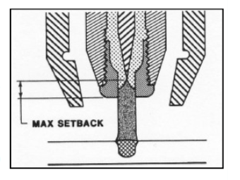
THIS TYPE OF WELD IS GENERALLY OBTAINED BY USING A STIFF. CONSTRICTED ARC. IN THE KEYHOLE MODE PENETRATION IS OBTAINED BY THE COMBINATION OF PLASMA AND GAS MOMENTUM WITH THERMAL CONDUCTION. WITH INCREASE PLASMA GAS FLOW RATED AND PLASMA SETBACK, A HOLE KNOWN AS THE KEYHOLE IS PIERCED THROUGH THE ENTIRE METAL THICKNESS AT THE LEADING EDGE OF THE WELD PUDDLE, WHERE THE FORCES OF THE PLASMA JET (COLUMN) DISPLACE TH E MOLTEN METAL. AS THE TORCH TRAVEL PROGRESSES AT A CONSISTENT SPEED, THE MOLTEN METAL, SUPPORTED BY THE SURFACE TENSION FLOWS BEHIND THE KEYHOLE TO FORM THE WELD BEAD.

KEYHOLE WELDING IS ALMOST EXCLUSIVELY PERFORMED IN THE AUTOMATED MODE. TYPICALLY THIS TECHNIQUE IS USED FOR SQUARE BUTT WELDS ON MATERIAL THICKNESS FROM 0.093”(2.4 MM) TO 0.250” (6.4 MM) REQU IRING 100% PENETRATION IN A SINGLE PASS. MANUAL KEYHOLE WEL DING IS NOT RECOMMENDED BECAUSE OF DIFFICULTIES IN MAINTAINING CONSISTENT TRAVEL SPEEDS, TORCH POSITION, OR FILLER MATERIAL ADDITION.


ADVANTAGES:

1) REDUCED CURRENT LEVE LS

2) SINGLE PASS WELDS

3) MINIMIZED WELD PREPA RATION

4) NARROWER WELD BEADS

5) VISUAL PROOF OF 100% PENETRATION

6) LESS FILLER MATERIAL REQUIRED

___________________________________

DISADVANTAGES:

(1) LIMITED TO FLAT, HORIZONTAL, AND VERTICAL UP POSIT IONS

2) MORE SENSITIVE TO VARIABLE CHANGES

3) LIMITED TO AUTOMA TED OPERATIONS

WELDING SAFETY 101

Eye Safety First 100% of the time.

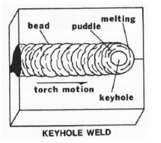
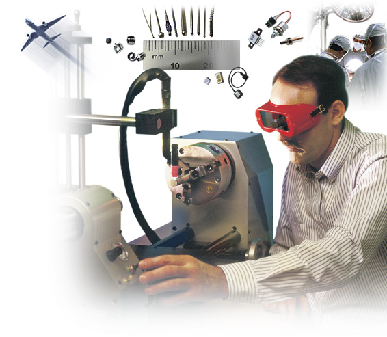
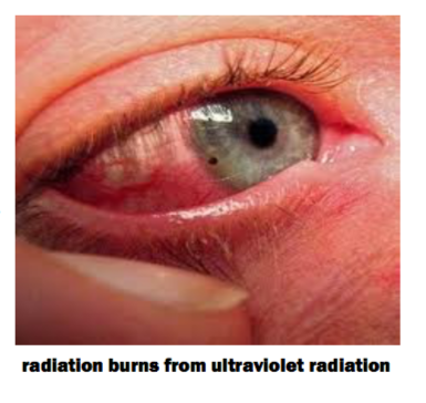
Eye injuries account for one – quarter of all welding injuries, making them by far the most common injury for welders. The best way to control eye injuries is also the most simple: proper selection and use of eye protection. Helmets alone do not offer enough protection. Welders should wear goggles or safety glasses with side shields that comply with ANSI Z87.1 under welding helmets and always wear goggles or other suitable eye protection when gas welding or oxygen cutting. To help in reducing eye injuries, you should educate workers about all of the dangers they face and should implement an eye protection plan that outlines proper welding behavior. Damage from ultraviolet light can occur very quickly. Normally absorbed in the cornea and lens of the eye, ultraviolet radiation (UVR) often causes arc eye or arc flash, a very painful but seldom permanent injury that is characterized by eye swelling, tearing, and pain. While most welding related eye injuries are reversible, with more than half of injured workers returning to work in less than two days and 95 percent in less than seven days, some eye injuries are irreversible and permanent visual impairment occurs. This is especially true with infrared and visible spectrum (bright light) radiation. Both can penetrate through to the retina and — although this is rare — can cause permanent retinal damage, including cataracts, diminished visual acuity, and higher sensitivity to light and glare.

As a general rule, select filter shades or lenses beginning with a shade too dark to see the welding zone. Then evaluate a lighter shade that provides adequate vision without going below the minimum protective shade. Most protective eyewear manufacturers offer 2.0, 3.0, and 5.0 filter shades, which protect against harmful optical radiation generated when working with molten metal, cutting, soldering, and brazing. A filter shade 2.0 lens allows 29 – 43 percent of light to be transmitted, filter shade 3.0 lenses allow 8.5 – 18 percent of light to be transmitted, and filter shade 5.0 lenses allow 1.8 – 3.6 percent of light to be transmitted. These shades are available in protective eyewear, goggles, and welding helmets.

To avoid ultraviolet skin burns protective clothing must be worn. The selection process for the most appropriate protective clothing for various welding and cutting operations will vary with the task size and location of the work to be performed. By carefully examining which hazards are possible, new technologies will often provide greater comfort, which can improve employee acceptance and increase wearing of the proper protective apparel.

WELDING FUMES

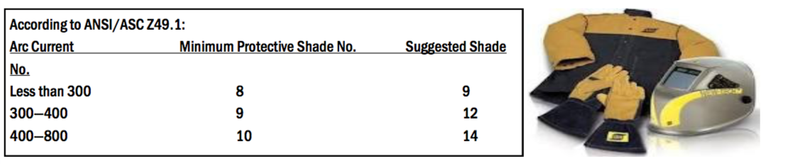
Welding fumes are very small particles that are formed when the vaporized metal rapidly condenses in air. They are typically too small to be seen by the naked eye but collectively form a visible plume. The health effects associated with metal fumes depend on the specific metals present in the fumes; they may range from short-term illnesses, such as metal fumes fever (i.e., flu-like symptoms), to long term lung damage and/ or neurological disorders. If the metal has been degreased with  chlorinated solvent, other airborne gases (such as phosgene, hydrogen chloride, chlorine gas, etc.) maybe produced. These gases generally cause irritated eyes , nose and respiratory system, and symptoms may be delayed. Always read the Material Safety Data Sheets supplied with the material you are using. These MSDSs will provide information regarding the kind and amount of fumes as gases that may be dangerous to your health. Fume extraction is the best way to remove dangerous fumes from your welding environment. There are many fume extractors on the market to choose from.
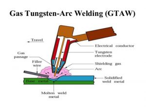
ELECTRIC SHOCK

The human body conducts electricity. Even low currents may cause severe health effects. Spasms, burns, muscle paralysis, or death can result depending on the amount of the current flowing through the body, the route it takes, and the duration of exposure.

If a person touches a live conductor, current may flow through the body to the ground and cause a shock. Increased electrical contact with the weld ground increases the risk of shock. Avoid standing in water, on wet surfaces, or working with wet hands or wearing sweaty garments. Small shocks could surprise you and cause you to slip and fall, possibly from a high place.

What should I do in case of electric shock?

Call for medical help. DO NOT touch the victim with y o ur “bare hands” until he or she is away from the live electrical source. Turn off the power at the fuse box or circuit breaker panel if an appliance or electrical equipment is the electrical source or, if you can do it safely, turn off the appliance or electrical equipment and unplug it. Just turning off the equipment is not sufficient. If the electricity cannot be turned off and the victim is still in contact with the electrical source, decide if you must move the victim or push the wire away from the victim (call for emergency help if the wire is a high voltage power line). Insulate yourself if you must move a victim away from a live contact – wear dry gloves or cover your hands with cloth and stand on dry insulating material like cardboard, wood or clothes. Ensure you have good footing and will not slip or fall when trying to move the victim. Do not move the victim if there is a possibility of neck injury (from a fall, for example) unless it is absolutely necessary. Give artificial respiration if the victim is not breathing.  Give CPR if the victim’s heart has stopped (only if you are trained in CPR).

Relationship between electrode and welding arc

How Is a Welding Arc Established?
A sequence of events takes place between the electrode and the piece being welded. To strike the welding arc, a high frequency generator is used to provide a high voltage, low current superimposed on the welding current. The effect is a spark which creates a conductive path through the shielding gas

Welding Electrodes

The electrode used in GTAW is made of tungsten or a tungsten alloy, because tungsten has the highest melting temperature among pure metals, at 3,422 °C (6,192 °F). As a result, the electrode is not consumed during welding, though some erosion (called burn-off) can occur. Electrodes can have either a clean finish or a ground finish—clean finish electrodes have been chemically cleaned, while ground finish electrodes have been ground to a uniform size and have a polished surface, making them optimal for heat conduction. The diameter of the electrode can vary between 0.5 and 6.4 millimetres (0.02 and 0.25 in), and their length can range from 75 to 610 millimetres (3.0 to 24 in).

Pure tungsten electrodes (classified as WP or EWP) are general purpose and low cost electrodes. They have poor heat resistance and electron emission. They find limited use in AC welding of e.g. magnesium and aluminum.

Cerium oxide (or ceria) as an alloying element improves arc stability and ease of starting while decreasing burn-off. Cerium addition is not

Using an alloy of lanthanum oxide (or lanthana) has a similar effect. Addition of 1% lanthanum has the same effect as 2% of cerium.

Thorium oxide (or thoria) alloy electrodes were designed for DC applications and can withstand somewhat higher temperatures while providing many of the benefits of other alloys. However, it is slightly radioactive. Inhalation of the thorium grinding dust during preparation of the electrode is hazardous to one’s health. Some electrode grinders have vacuum systems to prevent inhalation during grinding. As a replacement to thoriated electrodes, electrodes with larger concentrations of lanthanum oxide can be used. Larger additions than 0.6% do not have additional improving effect on arc starting, but they help with electron emission.

Higher percentage of thorium also makes tungsten more resistant to contamination.

Electrodes containing zirconium oxide (or zirconia) increase the current capacity while improving arc stability and starting and increasing electrode life. Zirconium-tungsten electrodes melt easier.

Ionized. A plasma exist during any arc occurrence. The energy level may vary enormously due to the ionization grade of the gas mixture. Essentially this spark allows the arc to be initiated

Were on the web www.pwsweld.com while the electrode and the work piece are separated.

APPLICATIONS OF PLASMA WELDING

When welding out gassing causes contamination of the tungsten electrode during GTAW welding and drastically shortens the life of tungsten electrode. Shortened electrode life decreases production time. When using PLASMA the electrode is protected . Tungsten electrode life is much longer and production is higher.

PLASMA stand off arc distance is not critical like It is with GTAW. The stand off arc distance can vary with PLASMA will still produce good welds. A good example is butt fusion edge welds of stainless steel. A well known client that manufacturers stainless steel thermos bottles was having problems welding the bottles with GTAW because of runout of the parts. PLASMA solved their production problems!

OFTEN OVERLOOKED PLASMA OFFERS SPEED AND AFFORDABILITY

If you have drawings / samples let us evaluate your part for PLASMA!

We Can Show you How to Implement a Production System so you can Better Compete Globally

Where we Stand Now.

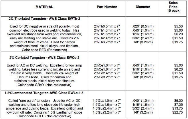
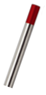
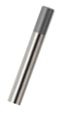
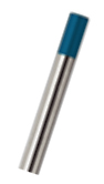
With international competition on the rise, how do you keep your customers coming back? In countries like China and India manufacturing exports continue to grow. These countries have implemented a new policy which emphasizes the development of domestic innovative capability. This has led to increased spending on R&D and a growing researcher base. Soon, not only will the part be available at a lower cost but at comparable quality as well. If developed countries are to remain competitive in the global economy, they will have to rely more on technology. Investment in technology is therefore a crucial factor for sustained economic health. A continuous process of change, innovation and productivity will allow you to be competitive as the global market continues to evolve. Innovate, or lose.

Whoever makes things better, cheaper, faster wins!

America must continue to be the leader.

STAYING COMPETITIVE

In order to compete with countries like China and India we need to adopt equipment and technology that will lower production cost while enhancing the product quality at the same time. Companies must now

look for new and innovative ways to improve their processes, their workers productivity, and, ultimately, their overall equipment effective- ness.

________________________________________________________________

LET PROCESS WELDING SYSTEMS HELP

BENEFITS OF AUTOMATED WELDING

With quality and productivity as buzzwords, and customers demanding superior products, implementing an automated welding system may determine whether a company remains competitive. Automating your welding production offer three main advantages: decreased variable labor costs, improved weld quality, and decreased scrap.

Decreased Variable Labor

ImprovedWeld Quality:

Mechanized welding improves weld integrity and repeatability. Humans tend to “smooth over” a mistake with the torch, hiding lack of penetration or a possible flawed weld.

Decreased Scrap/Rework:

It’s never good to throw away parts with accumulated significant value because of a welders lack of detail. Automating weld parameters and part placement decreased the error potential.

Costs: Amachinecontrolledsys- tem always repeats the same welding parameters. Reliance on human welders dramatically in- creases a manufacturer’s labor costs. A fully automatic system with sufficient stations can run at four or at eight times the pace of a skilled welder.

A fully automatic system with sufficient stations can run at four or at eight times the pace of a skilled welder.

SOME OF OUR CUSTOMERS

  •   General Atomics
  •   Teledyne Energy
  •   McKenna Machine
  •   Delphi Automotive
  •   Fuel Cell Energy Corp.

 Angio-Dynamics
 Pratt & Whitney
 Parker Hannifin Corp.  Lake Region
 Draper Laboratory

What You Need To Know About Gas Regulators

What Is The Difference Between Single Stage and Dual Stage Regulators

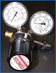
Gas pressure regulators are used to reduce the pressure of gas supplied from a high-pressure cylinder of gas to a workable level that can be safely used for operating equipment and instruments. There are two basic types of gas pressure regulators: single-stage and two-stage. Single-stage pressure regulators reduce the cylinder pressure to the delivery or outlet pressure in one step.

Two-stage pressure regulators reduce the cylinder pressure to a working level in two steps. Since the performance of each is influenced by mechanical characteristics, the choice of gas regulator depends on the type of application for which it is intended.

The two most important parameters to be considered are droop and supply pressure effect.

Droop is the difference in delivery pressure between zero flow conditions and the gas regulator’s maximum flow capacity. Supply pressure effect is the variation in delivery pressure as supply pressure decreases while the cylinder empties. For most regulators, a decrease in inlet pressure causes the delivery pressure to increase.

The effect of these differences on performance can be illustrated with some examples. For instance, when a centralized gas delivery system is supplying a number of different chromatographs, flow rates are apt to be fairly constant. Supply pressure variations, however, may be abrupt especially when automatic changeover manifolds are used. In this scenario, a two-stage regulator with a narrow accuracy envelope (supply pressure effect) and a relatively steep droop should be used to avoid a baseline shift on the chromatographs.

Single-stage and two-stage gas regulators have different droop characteristics and respond differently to changing supply pressure. The single-stage regulator shows little droop with varying flow rates, but a relatively large supply pressure effect. Conversely, the two-stage regulator shows a steeper slope in droop but only small supply pressure effects.

On the other hand, if gas is being used for a short duration instrument calibration, a single-stage gas regulator with a wide accuracy envelope (supply pressure effect) but a comparatively flat droop should be chosen. This will eliminate the need to allow the gas to flow at a constant rate before the calibration can be done.

High Purity Gas Regulators

The ideal construction for high-purity gas service is a gas regulator that has a stainless steel diaphragm. Such regulators are non-contaminating and assure satisfactory use for all applications of noncorrosive and mildly corrosive gases.

Regulators for corrosive gases must be selected from those recommended with each gas listing. A gas regulator equipped with a stainless steel diaphragm has several advantages over the elastomeric type. It does not outgas organic materials and it also prevents the diffusion of atmospheric oxygen into the carrier gas. Both Buna-N and Neoprene diaphragms are permeable to oxygen. The chemical potential of oxygen between the carrier gas and the atmosphere provides sufficient driving force for oxygen to intrude the carrier gas through a permeable diaphragm.