What Is The Difference Between Single Stage and Dual Stage Regulators
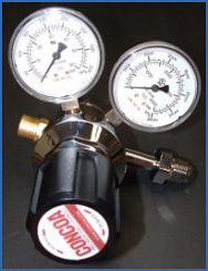 Gas pressure regulators are used to reduce the pressure of gas supplied from a high-pressure cylinder of gas to a workable level that can be safely used for operating equipment and instruments. There are two basic types of gas pressure regulators: single-stage and two-stage. Single-stage pressure regulators reduce the cylinder pressure to the delivery or outlet pressure in one step.
Two-stage pressure regulators reduce the cylinder pressure to a working level in two steps. Since the performance of each is influenced by mechanical characteristics, the choice of gas regulator depends on the type of application for which it is intended.
The two most important parameters to be considered are droop and supply pressure effect.
Droop is the difference in delivery pressure between zero flow conditions and the gas regulator’s maximum flow capacity. Supply pressure effect is the variation in delivery pressure as supply pressure decreases while the cylinder empties. For most regulators, a decrease in inlet pressure causes the delivery pressure to increase.
The effect of these differences on performance can be illustrated with some examples. For instance, when a centralized gas delivery system is supplying a number of different chromatographs, flow rates are apt to be fairly constant. Supply pressure variations, however, may be abrupt especially when automatic changeover manifolds are used. In this scenario, a two-stage regulator with a narrow accuracy envelope (supply pressure effect) and a relatively steep droop should be used to avoid a baseline shift on the chromatographs.
Single-stage and two-stage gas regulators have different droop characteristics and respond differently to changing supply pressure. The single-stage regulator shows little droop with varying flow rates, but a relatively large supply pressure effect. Conversely, the two-stage regulator shows a steeper slope in droop but only small supply pressure effects.
On the other hand, if gas is being used for a short duration instrument calibration, a single-stage gas regulator with a wide accuracy envelope (supply pressure effect) but a comparatively flat droop should be chosen. This will eliminate the need to allow the gas to flow at a constant rate before the calibration can be done.
High Purity Gas Regulators
The ideal construction for high-purity gas service is a gas regulator that has a stainless steel diaphragm. Such regulators are non-contaminating and assure satisfactory use for all applications of noncorrosive and mildly corrosive gases.
Regulators for corrosive gases must be selected from those recommended with each gas listing. A gas regulator equipped with a stainless steel diaphragm has several advantages over the elastomeric type. It does not outgas organic materials and it also prevents the diffusion of atmospheric oxygen into the carrier gas. Both Buna-N and Neoprene diaphragms are permeable to oxygen. The chemical potential of oxygen between the carrier gas and the atmosphere provides sufficient driving force for oxygen to intrude the carrier gas through a permeable diaphragm.
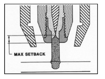 THIS TYPE OF WELD IS GENERALLY OBTAINED BY USING A STIFF. CONSTRICTED ARC. IN THE KEYHOLE MODE PENETRATION IS OBTAINED BY THE COMBINATION OF PLASMA AND GAS MOMENTUM WITH THERMAL CONDUCTION. WITH INCREASE PLASMA GAS FLOW RATED AND PLASMA SETBACK, A HOLE KNOWN AS THE KEYHOLE IS PIERCED THROUGH THE ENTIRE METAL THICKNESS AT THE LEADING EDGE OF THE WELD PUDDLE, WHERE THE FORCES OF THE PLASMA JET (COLUMN) DISPLACE TH E MOLTEN METAL. AS THE TORCH TRAVEL PROGRESSES AT A CONSISTENT SPEED, THE MOLTEN METAL, SUPPORTED BY THE SURFACE TENSION FLOWS BEHIND THE KEYHOLE TO FORM THE WELD BEAD.
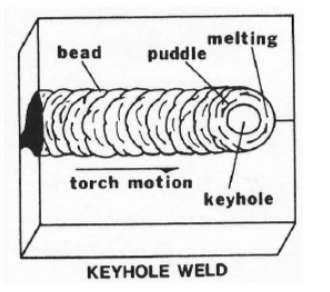
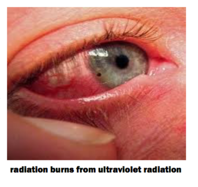 Eye injuries account for one – quarter of all welding injuries, making them by far the most common injury for welders. The best way to control eye injuries is also the most simple: proper selection and use of eye protection. Helmets alone do not offer enough protection. Welders should wear goggles or safety glasses with side shields that comply with ANSI Z87.1 under welding helmets and always wear goggles or other suitable eye protection when gas welding or oxygen cutting. To help in reducing eye injuries, you should educate workers about all of the dangers they face and should implement an eye protection plan that outlines proper welding behavior. Damage from ultraviolet light can occur very quickly. Normally absorbed in the cornea and lens of the eye, ultraviolet radiation (UVR) often causes arc eye or arc flash, a very painful but seldom permanent injury that is characterized by eye swelling, tearing, and pain. While most welding related eye injuries are reversible, with more than half of injured workers returning to work in less than two days and 95 percent in less than seven days, some eye injuries are irreversible and permanent visual impairment occurs. This is especially true with infrared and visible spectrum (bright light) radiation. Both can penetrate through to the retina and — although this is rare — can cause permanent retinal damage, including cataracts, diminished visual acuity, and higher sensitivity to light and glare.
 Welding fumes are very small particles that are formed when the vaporized metal rapidly condenses in air. They are typically too small to be seen by the naked eye but collectively form a visible plume. The health effects associated with metal fumes depend on the specific metals present in the fumes; they may range from short-term illnesses, such as metal fumes fever (i.e., flu-like symptoms), to long term lung damage and/ or neurological disorders. If the metal has been degreased with chlorinated solvent, other airborne gases (such as phosgene, hydrogen chloride, chlorine gas, etc.) maybe produced. These gases generally cause irritated eyes , nose and respiratory system, and symptoms may be delayed. Always read the Material Safety Data Sheets supplied with the material you are using. These MSDSs will provide information regarding the kind and amount of fumes as gases that may be dangerous to your health. Fume extraction is the best way to remove dangerous fumes from your welding environment. There are many fume extractors on the market to choose from.
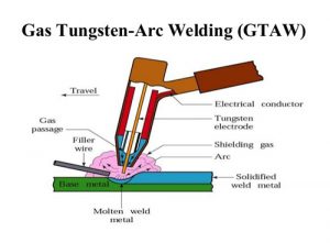 Welding Electrodes

 With international competition on the rise, how do you keep your customers coming back? In countries like China and India manufacturing exports continue to grow. These countries have implemented a new policy which emphasizes the development of domestic innovative capability. This has led to increased spending on R&D and a growing researcher base. Soon, not only will the part be available at a lower cost but at comparable quality as well. If developed countries are to remain competitive in the global economy, they will
  Decreased Variable Labor