Controller Automation Services

If you are looking for automated controller solutions Process Welding Systems is a leader as a manufacturer and distributor of precision automated welding systems.

Since 1993 Process Welding Systems (PWS) has developed a variety of products and many of the products we offer are of a “value added” nature. PWS is able to assist customers in improving their production processes through equipment to enhance or improve welding quality. We are skilled in recommending solutions to complex welding applications is highly regarded by customers and competition. We can provide turnkey solutions for your Human Machine Controllers (HMI) and Programmable Logic Controller (PLC) controller needs.

SERVICES INCLUDE:
• Design services for precision welding systems (manual load/unload or semi-automatic)
• Integration of welding system accessories & site installation assistance
• Experienced staff for custom design & manufacture of tooling, fixtures & specialty torch nozzles
• Free weld application review & process recommendation

We specialize in automation manufacturing in several industries and whether it is a solution to an automation problem or a turnkey project call PWS for the best solution.  From automotive to the medical device industry and PWS has experience in electrical design engineering and we work with Shafer Industrial Automation which are a valued source to provide maintenance / production support, PLC / HMI and robotic programming, ACAD electrical design, as well as full turnkey custom and repeat / “build to print” automation machine design, build, deliver and install.


Experience including but not limited to –

• Specialized in Allen Bradley platforms – PLC’s and HMI’s

•  All formats of HMI’s.

• Additional experience with Omron, Mitsubishi, Keyence, Automation Direct Click / Directlogic

• Fanuc robots – vision / non-vision systems, pick & place and welding systems.

• Additional experience with Motoman, Panasonic, ABB, Epson robotics.

• Keyence and Cognex vision systems.

• ACAD electrical design.


Markets including but not limited to –

• Medical equipment

• Aircraft & aerospace

• Automotive

• Instrumentation

• Lighting

Call us today or Contact us at your convenience at : Contact Us

IMPORTANT NOTICE

The DT-100 and the Ultima 150 are no longer supported by Process Welding Systems.

Repair of the DT-100 is very limited with little or no parts available.   It has been replaced by the DT-400 Click For DT-400 Data Sheet or the Weld-Pro

Click For Weld PRO Data Sheet Delivery is 5-6 weeks for either unit.  Please take action now to avoid unnecessary down time.


The Ultima-150 is no longer available.

Repair of the Ultima-150 is very limited with little or no parts available.  It has been replaced by the SanPaw 150 Click For SanPAW 150 Data Sheet or the Dual Arc Click For Dual Arc Data Sheet (see attached).  Delivery is 8-9 weeks for the Dual Arc and 3-4 for the SanPaw 150 unit.  Please take action now to avoid unnecessary down

DT-400 Control for Plasma & TIG Welding

The Weld-Pro Programmer


The SanPaw 150

Dual Arc 82


SANPAW 150PW AND PLASMA WELDING

The alternative to Plasma and Laser and the Ultima 150.The 150PW Plasma Arc Welding System is self-contained in a small package with a 200 Amp power supply, control console and Recirculator with many advantages over traditional automated plasma welding. It’s pilot arc circuit results in consistent arc starting every time, reduced scrap and improved process control for repeatable, high quality welds.Easy to setup: just requires attaching input power, gases, then mounting the torch.
Features and Benefits:
• 0.5-200 Amp current range – providing quality performance on a wide variety of applications.
•.Smooth DC arc – repetitive, high quality welds.•.Pilot Arc – repeatable arc starting reducing defects and rework .

•.Multiple Voltage Input – 200-230/460VAC, 1/3 phase, 50 or 60 hz (575VAC with optional module)

• Current Limiter – limits power source output to torch capability to avoid torch damage.

• Preview Set Current – eliminates costly test set-ups/displays actual current/voltage.

• Included Weld Sequencer (Current Sloper/Pulser).

• Internal Torch Coolant Recirculator.

• Save 9 Programs.

• Protection devices:

• Coolant flow protection/interlock

• Coolant temperature protection/interlock

• Console temperature overload detection/interlock

• Simple interface – automated or manual control

• Can utilize a number of competitive torches.

• Approvals — CSA (pending); IP23S; IEC 60974-1 (CE)

• 3 Year Warranty

Part Number: IDU-W150PW-U1DVP (Power Supply Only.)

The SanPAW 150 PDF Brochure

Contact us for more detailed information about plasma welding or call us at 615.793.7020.

New Plasma Console 400 HFP

Plasma Console 400 HFP

Plasma OR TIG Welding

Add Plasma to Your Shop Using Your DC TIG Power Supply
Update Your Old Existing Console:
• Easy to Use
• Plasma & TIG Complete Cycle
• Built-In Memory for 10 Jobs 
• Pulsation
• Robot Connection
• ModBus Connection
• Small Compact Design 

We also offer water chillers and plasma torches to complete your plasma welding system.
We are here to help. Rely on:
Process Welding Systems, Inc.

Take Control With The Weld-Pro

ACCESSORY SCREEN


POWER SUPPLY


PARAMETERS CONTROLLED:

The Process Welding “WELD PRO” weld controller makes quick and easy work of changing from job to job with multiple devices. CAPABILITIES:

Control welding power supply, lathe or other motion device, AVC, wire feeder and aux gas from one location with either Modbus or
0 - 10V / analog signals!

• Pre-gas
• Initial Current
• Upslope
• Welding Current
• Pulsation Parameters
• Final Current
• Post-Gas
• Wire Start Delay
• Wire Speed
• Burnback Time
• Arc Gap Setting
• Arc Voltage
• AVC Start Delay
• Lathe Speed
• Lathe Start Delay

Let Us Help You Implement a Production System That Will Compete With the Growing Overseas Market

Where We Stand Now

With international competition on the rise, how do you keep your customers coming back? In countries like China and India manufacturing exports continue to grow. These countries have implemented a new policy which emphasizes the development of domestic innovative capability.

This has led to increased spending on R&D and a growing researcher base. Soon, not only will the part be available at a lower cost but at comparable quality as well. If developed countries are to
remain competitive in the global economy, they will have to rely more on technology. Investment in technology is therefore a crucial factor for  sustained economic health. A continuous process of change, innovation and productivity will allow you to be competitive as the global market continues to evolve. Innovate, or lose.


Whoever makes things better, cheaper, faster wins! America must continue to bethe leader.


Staying Competitive

In order to compete with countries like China and India we need to adopt equipment and technology that will lower production cost while enhancing the product quality at the same time. Companies must now look for new and innovative ways to improve their processes, their workers productivity and, ultimately, their overall equipment effectiveness.

Let PWS Help

With quality and productivity as buzzwords, and customers demanding superior products, implementing an automated welding system may determine whether a company remains competitive. Automating your welding production offer three main advantages: decreased variable labor costs, improved weld quality and decreased scrap.

Benefits of Automated Welding

Decreased Variable Labor Costs: A machine controlled system always repeats the same welding parameters. Reliance on human welders dramatically increases a manufacturer’s labor costs. A fully automatic system with sufficient stations can run at four or at eight times the pace of a skilled welder.

Improved Weld Quality: Mechanized welding improves weld integrity and repeatability. Humans tend to “smooth over” a mistake with the torch, hiding lack of penetration or a possible flawed weld.

Decreased Scrap/Rework: It’s never good to throw away parts with accumulated significant value because of a welders lack of detail. Automating weld parameters and part placement decreased the error potential.


A fully automatic system with sufficient stations can run at four or at eight times the pace of a skilled welder.


Some of Our Customers

  • General Atomics
  • Teledyne Energy
  • McKenna Machine
  • Delphi Automotive
  • Fuel Cell Energy Corp.
  • Angio-Dynamics
  • Pratt & Whitney
  • Parker Hannifin Corp.
  • Lake Region
  • Draper Laboratory

Low AMP Plasma Welding Check List for Contaminated Electrode, Dirty Weld Nozzles and Plasma Torch Care.

Where We Stand Now

  1. A dark blue or black tungsten (Figure B) is a sign of moisture or oxygen getting into the plasma gas line (also called the pilot gas line). If the gas is good quality and the gas lines are leak free the tungsten should remain a gray color (Figure A) not dark blue or black. Moisture and oxygen in the gas lines deteriorate the tungsten electrode and thus the number of arc starts that the tungsten electrode can produce is reduced. This cuts down on the number of arc starts in production and decreases production.
  2. Any leaks in the gas lines or fittings can allow air to be sucked into the gas system which adds oxygen and moisture to the welding gases being used. Levels of oxygen and water should be less than 5ppm. The most important gas in plasma welding is the pilot gas, also called plasma gas, is always argon gas. The grade of argon being used should be at least 99.998% pure argon. In plasma welding if the gas is not pure it will contaminate the tungsten electrode and turn the tungsten electrode a dark blue and black color. If the problem is very severe the discoloration will run all the way to the point of the tungsten electrode and the nozzles on the torch will clog up.

  3. To check for gas leaks one needs to install a bottle of gas on the pilot gas line and it is recommended that the gas bottle is used with a dual stage regulator with a stainless steel diaphragm. Next take a nozzle for the torch and solder the orifice of the nozzle closed. Clean the nozzle after soldering with acetone or alcohol and install a small o’ring that will make a seal when the nozzle is screwed into the torch and hand tightened Also make sure that where the nozzle seats against the torch body is clean and free of dirt. If the nozzle does not seat well against the torch body a gas leak can occur. Turn the pilot gas flowmeter up to its highest flow and turn off the argon gas bottle. This will trap gas in between the tip of the torch nozzle and the argon gas bottle. Take a reading on the high pressure gas gauge of the gas regulator. Wait 15 to 30 minutes. If the gas system is leak free the gauge reading will stay the same as when the gas bottle was turned off. If the gauge pressure drops then there is a gas leak in the system. The leak could be caused by a hole in the gas hoses or defective fittings and gaskets.

  4. If the system has a leak you must then go through and check fittings to make sure they are tight and make sure that gaskets are sealing. You can also pinch the plastic hose where the torch connects and trap gas from where the hose is pinched back to the regulator and see if still leaks thus working your back through the gas system.

  5. Check for cracks in the torch body. If the torch has a back cap check the o’ring on the cap and check the cap for holes or cracks.

  6. After it has been determined that the gas system is leak free the system needs to be purged. By purging the gas lines it will clean all of the moisture and oxygen out of the lines so that you will only have good clean gas in the system. Turn the pilot gas flow up to its highest flow rate and let the gas run through the lines for at least 30 minutes to and hour. Next start a pilot arc and let it run at normal pilot arc gas settings (0.4 to 0.6 liters per minute) for 10 minutes. Turn off the pilot arc and check to see if the color of the tungsten electrode is gray. If it is gray your gas system is clean. If the color is black and blue then the system needs to purge longer to make sure it is clean.

  7. If your welding system is shut down over night air with oxygen and moisture will get up inside the plasma torch. Before starting to weld on the next day you need to again purge the gas lines approximately 5 to 10 minutes before starting to weld. You may want to turn the pilot gas down to a very low flow such as 0.1 liters per minute and let the gas run all night to keep the gas line clean. It will be such a low flow that it will not be of any economic importance.

  8. When the pilot arc is turned off let the gas continue to flow for at least 10 to 15 seconds before turning off main power. The gas flow will keep the tungsten electrode from oxidizing until it cools down.

  9. Whenever thinking about electrode life, electrode contamination, ease of arc starting and arc stability you should not forget that the exchange of ions takes place within the plasma column in both directions which is from the electrode to the work piece and from the work piece to the electrode. If impurities such as lead, sulfur, aluminum, magnesium, copper, zinc, brass, oil, grease or any other dirty elements are on or in the material being welded they will contaminate the tungsten electrode and nozzle. You then cannot count on a maximum number of welds before replacing the tungsten electrode and weld nozzle.

  10. Clean the nozzle orifice with acetone or alcohol and a Q-tip. A round wooden toothpick can be used to clean the orifice of the nozzle. Weld nozzles trap contamination during welding and will need to be cleaned every time the tungsten is re-ground.

  11. The pilot arc should be bright white with a light blue tint color. If the color changes to orange or purple that is a sign of contamination. Also the pilot arc will draw back into the nozzle, which is a sign that the tungsten electrode has deteriorated.

  12. WARNING: It is extremely important that when tightening the nozzle onto the torch head that you do not over tighten the nozzle and strip the threads. Copper is a very soft material, which makes it easier to over tighten the nozzle. Tighten the nozzle until it barely makes intimate contact with the end of the torch head. It is recommended that pliers be used to tighten the nozzle but be careful not to grab the torch head with the pliers. Also be careful not to cross thread the nozzle. If the nozzle is cross threaded it will damage the threads inside the torch head. Do not get dirt, grease or oil inside the torch head or on the nozzle threads, which will damage the threads in the torch head. If the torch head is damaged by the pliers it can cause a gas leak between the nozzle and torch head and the nozzle will not seat properly against the water cooled part of the torch head. If the threads are stripped and the torch head is damaged the torch will have to be replaced. Periodically clean the inside of the torch and thread where the nozzle seat with alcohol of acetone. Make sure that the technician that handle the torch and installs nozzles hands are clean. Dirt, oil, grease and grit is not acceptable on any of the torch parts. The plasma welding torch is an expensive device and should handled with great care.

  13. The type of hose material that the pilot gas and shield gas are passed through is very important. All plastics can have moisture and oxygen that diffused through the walls of the hose material. When welding sensitive materials such as titanium the welding system may need to plumbed with stainless steel gas lines.

Plasma Welding Summary

The plasma welding process was introduced to the welding industry in 1964 as a method of bringing better control to the arc welding process in lower current ranges. Today, plasma retains the original advantages it brought to industry by providing an advanced level of control and accuracy to produce high quality welds in miniature or precision applications.

The plasma process is equally suited to manual and automatic applications. It has been used in a variety of operations ranging from high volume welding of strip metal, to precision welding of surgical instruments, to automatic repair of jet engine blades, to the manual welding of kitchen equipment for the food and dairy industry.

How Plasma Welding Works:

A plasma is a gas which is heated to an extremely high temperature and ionized so that it becomes electrically conductive. The plasma arc welding process uses this plasma to transfer an electric arc to a work piece. The metal to be welded is melted by the intense heat of the arc and fuses together.

The system requires a power supply and welding torch. In the torch an electrode is located within a torch nozzle having a small opening at the tip. A pilot arc is initiated between the torch electrode and nozzle tip. Gas is fed through the nozzle where the pilot arc heats the gas to the plasma temperature range and ionizes it. The gas emerges from the nozzle in the form of a jet, hotter than any chemical flame or conventional electric arc. The main welding arc transfers to the work piece through this column of plasma gas.

Plasma gases are normally argon. The torch also uses a secondary gas, argon, argon/hydrogen or helium which assists in shielding the molten weld puddle thus minimizing oxidation of the weld.

By forcing the plasma gas and arc through a constricted orifice, the torch delivers a high concentration of heat to a small area. With suitable equipment the process produces exceptionally high quality cuts on a variety of materials.

Plasma Welding Features & Benefits:


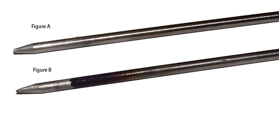
F: Protected electrode

B: Protected electrode allows for less electrode contamination. This is especially advantageous in welding .materials that out gas when welded and contaminate the unprotected GTAW electrode.


F: Length of arc benefit due to arc shape and even heat distribution

B: Arc stand off distance is not as critical as in GTAW. Gives good weld consistency. No AVC needed in 99% of distribution applications, sometimes even with wirefeed.


F: Arc transfer is gentle and and consistent

B: Provides for welding of thin sheet, fine wires, miniature components where the harsh GTAW arc start would damage the part to be welded.


F: Stable arc in welding

B: Reduces arc wander. Arc welds where it is aimed. Allows and arc starting tooling in close proximity to weld joint for optimum heat sinking.


F: Minimal high frequency noise in welding

B: Minimal high frequency noise once pilot arc started, thus plasma can be used with NC controls. Another benefit lies in welding applications involving hermetic sealing of electronic components where the GTAW arc start would cause electrical disturbances possibly damaging the electronic internals of the component to be welded.


F: Arc energy density reaches 3 times that of TIG

B: Causes less weld distortion and smaller welds. Gives high welding speeds


F: Weld times as short as .005 seconds

B: Extremely short and accurate weld times possible for spot seconds welding of fine wires, accurate weld times combined with precision motion devices provide for repeatable weld start/stop positions.


F: Equipment options offer up to 10,000 Hz

B: Offers a wide range of pulsing options for varied, pulsing applications.


F: Low amperage art welding (as low as 0.05 amp)

B: Allows welding of miniature components or good control in downsloping to a weld edge.


F: Arc diameter chosen via nozzle orifice

B: This feature assists in predicting the weld bead size.


Plasma Welding Features, Benefits & Applications

Features & Benefits:

P Protected electrode, offers long times before electrode maintenance (usually one 8 Hr Shift)

L Low amperage welding capability (as low as 0.05 amp)

A Arc consistency and gentle arc starting produce consistent welds, time after time

S Stable arc in arc starting and low amperage welding

M Minimal high frequency noise issues, HF only in pilot arc start, not for each weld

A Arc energy density reaches 3 times that of GTAW. Higher weld speeds possible

W Weld times as short as 5 msecs (.005 secs)

E Energy density reduces heat affected zone, improves weld quality

L Length of arc benefit due to arc shape and even heat distribution

D Diameter of arc chosen via nozzle orifice


Metals that plasma can weld include stainless, heat resistant and other steels, titanium, Inconel, Kovar, zircalloy, tantalum, copper, brass, gold and silver.


Applications:

The benefits of the plasma process offers two prime benefits: Increased welding speed and improved weld quality. Plasma is excellent for welding wires, tubes, strips, sheets, and all miniature, medium and large components requiring precision welding. In many applications, many of the unique advantages of plasma combine to benefit the welding process.

Wire Welding: The plasma process can gently yet consistently start an arc to the tip of wires or other small components and make repeatable welds with very short weld time periods.

Strip Metal Welding: The plasma process provides the ability to consistently transfer the arc to the workpiece and weld up to the edges of the weld joint. In automatic applications no Arc Distance Control is necessary for long welds and the process requires less maintenance to the torch components. This is especially advantageous in high volume applications where the material outgases or has surface contaminants.

Sealed Components: Medical and electronic components are often hermetically sealed via welding. The plasma process provides the ability to;
1. Reduce the heat input to the part
2. Weld near delicate insulating seals
3. Start the arc without high frequency electrical noise which could be damaging to the electrical internals

Precision Instruments: Many instruments require welds of great accuracy. Plasma welding, with its control and precision, provides the ability to make these critical welds.


Other Plasma Welding Applications

Surgical Instruments, Needles, Wires, Light Bulb Filaments, Thermocouples, Probes, Pressure and Electrical Sensors, Bellows, Seals, Cans, Enclosures, Microswitches, Valves, Electronic Components, Motors, Batteries, Miniature Tube to Fitting/Flange, Food and Dairy Equipment, Tube Mill Applications, Tool Die & Mold Repair.


Comparison of GTAW & Plasma Welding Energy Input

Test Parameters: Manual welding, no clamping device, Cr/Ni steel, 0.102″ thickness; all values determined with measuring instruments.

GTAW: 125 Amps 12 Volts 10.24 I.P.M.
Plasma: 75 Amps 18 Volts 13.38 I.P.M.
Heat Input: V x A x 60


Speed in cm/min

GTAW: 12 x 125 x 60


Speed in cm/min

= 3.46 KJ
Heat Input: 18 x 75 x 60


34 cm/min

= 2.38 KJ

In addition to the fact that a higher weld speed is possible, the lower heat input brings the following advantages:


  • Less distortion
  • Less stress in welded component
  • Less tempering color with Cr/Ni steels
  • Lower risk of damaging any heat sensitive parts adjacent to the weld joint