Controller Automation Services

If you are looking for automated controller solutions Process Welding Systems is a leader as a manufacturer and distributor of precision automated welding systems.
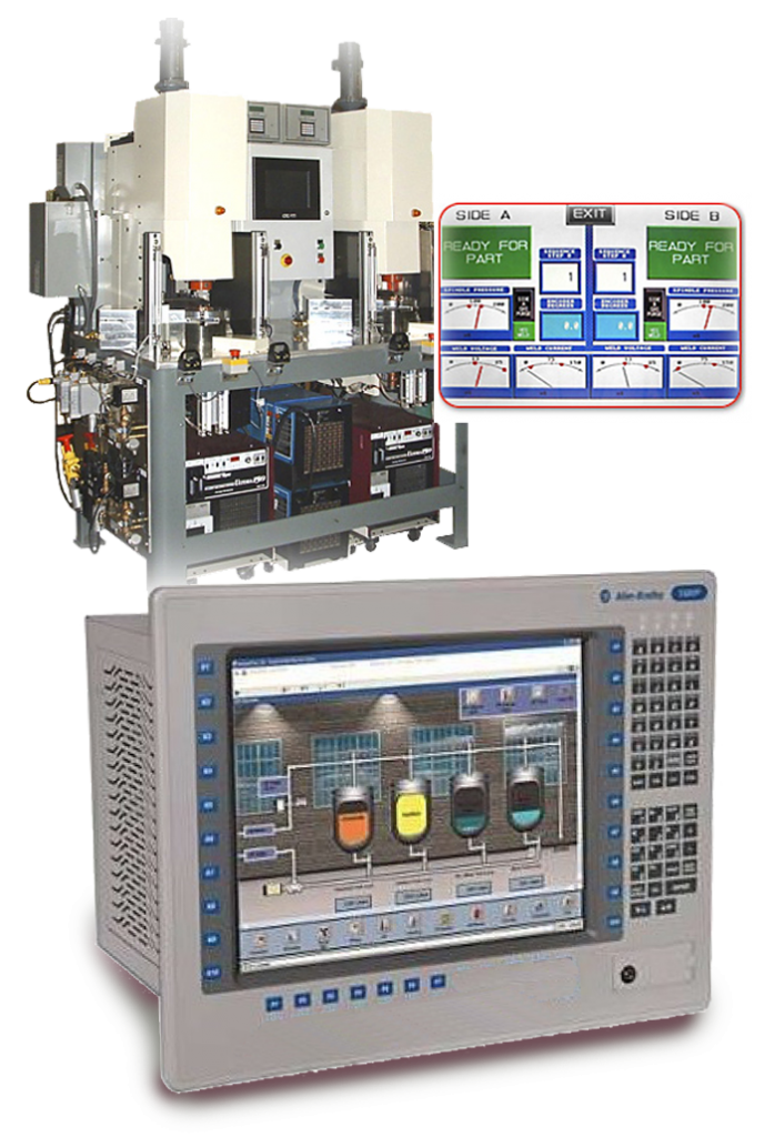
Since 1993 Process Welding Systems (PWS) has developed a variety of products and many of the products we offer are of a “value added” nature. PWS is able to assist customers in improving their production processes through equipment to enhance or improve welding quality. We are skilled in recommending solutions to complex welding applications is highly regarded by customers and competition. We can provide turnkey solutions for your Human Machine Controllers (HMI) and Programmable Logic Controller (PLC) controller needs.

SERVICES INCLUDE:
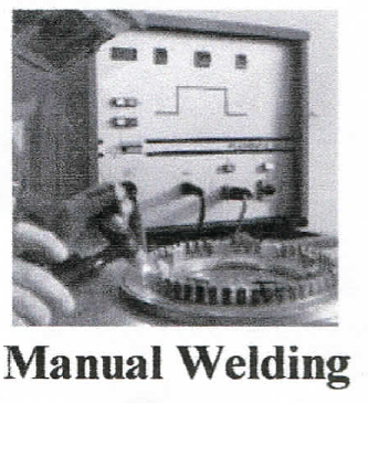
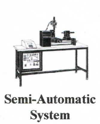
• Design services for precision welding systems (manual load/unload or semi-automatic)
• Integration of welding system accessories & site installation assistance
• Experienced staff for custom design & manufacture of tooling, fixtures & specialty torch nozzles
• Free weld application review & process recommendation

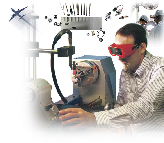
We specialize in automation manufacturing in several industries and whether it is a solution to an automation problem or a turnkey project call PWS for the best solution.  From automotive to the medical device industry and PWS has experience in electrical design engineering and we work with Shafer Industrial Automation which are a valued source to provide maintenance / production support, PLC / HMI and robotic programming, ACAD electrical design, as well as full turnkey custom and repeat / “build to print” automation machine design, build, deliver and install.
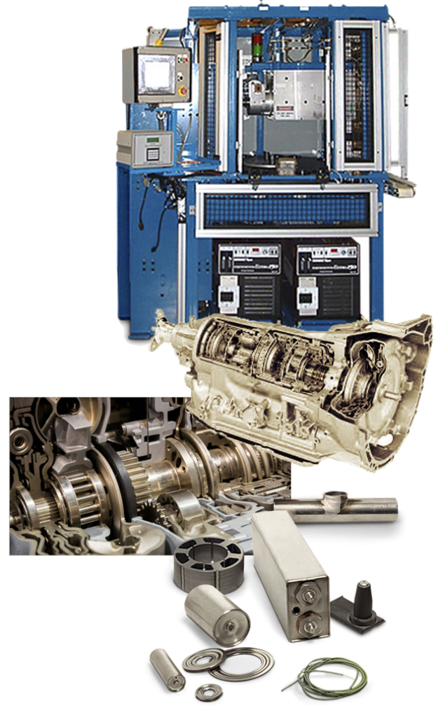

Experience including but not limited to –

• Specialized in Allen Bradley platforms – PLC’s and HMI’s

•  All formats of HMI’s.

• Additional experience with Omron, Mitsubishi, Keyence, Automation Direct Click / Directlogic

• Fanuc robots – vision / non-vision systems, pick & place and welding systems.

• Additional experience with Motoman, Panasonic, ABB, Epson robotics.

• Keyence and Cognex vision systems.

• ACAD electrical design.


Markets including but not limited to –

• Medical equipment

• Aircraft & aerospace

• Automotive

• Instrumentation

• Lighting

Call us today or Contact us at your convenience at : Contact Us

IMPORTANT NOTICE

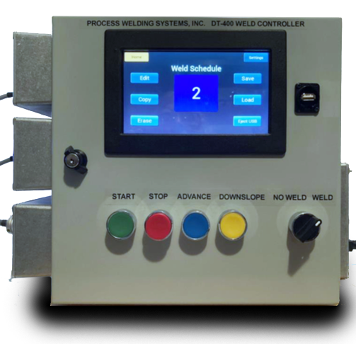
The DT-100 and the Ultima 150 are no longer supported by Process Welding Systems.

Repair of the DT-100 is very limited with little or no parts available.   It has been replaced by the DT-400 Click For DT-400 Data Sheet or the Weld-Pro

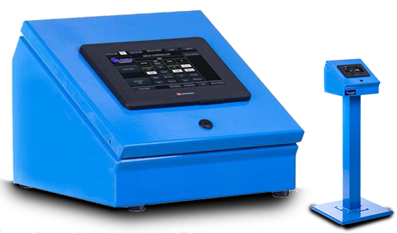
Click For Weld PRO Data Sheet Delivery is 5-6 weeks for either unit.  Please take action now to avoid unnecessary down time.


The Ultima-150 is no longer available.

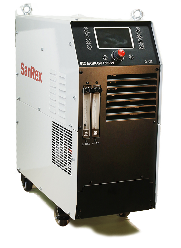
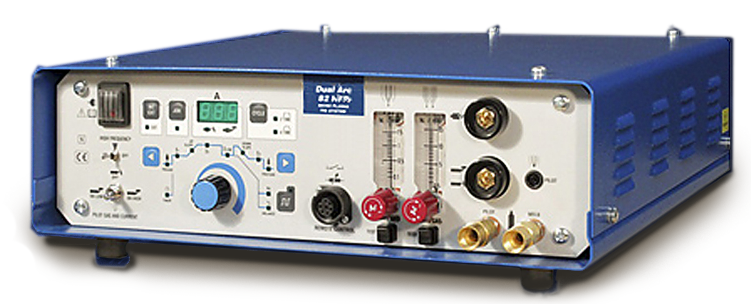
Repair of the Ultima-150 is very limited with little or no parts available.  It has been replaced by the SanPaw 150 Click For SanPAW 150 Data Sheet or the Dual Arc Click For Dual Arc Data Sheet (see attached).  Delivery is 8-9 weeks for the Dual Arc and 3-4 for the SanPaw 150 unit.  Please take action now to avoid unnecessary down

DT-400 Control for Plasma & TIG Welding

The Weld-Pro Programmer


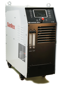
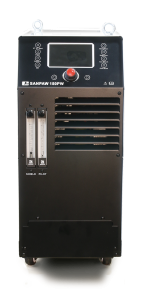
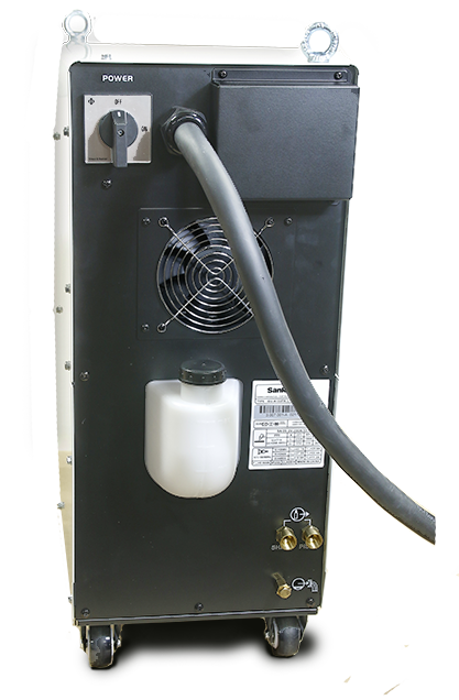
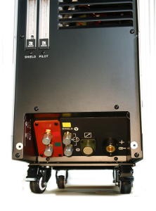
The SanPaw 150

Dual Arc 82


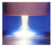
SANPAW 150PW AND PLASMA WELDING

The alternative to Plasma and Laser and the Ultima 150.The 150PW Plasma Arc Welding System is self-contained in a small package with a 200 Amp power supply, control console and Recirculator with many advantages over traditional automated plasma welding. It’s pilot arc circuit results in consistent arc starting every time, reduced scrap and improved process control for repeatable, high quality welds.Easy to setup: just requires attaching input power, gases, then mounting the torch.
Features and Benefits:
• 0.5-200 Amp current range – providing quality performance on a wide variety of applications.
•.Smooth DC arc – repetitive, high quality welds.•.Pilot Arc – repeatable arc starting reducing defects and rework .

•.Multiple Voltage Input – 200-230/460VAC, 1/3 phase, 50 or 60 hz (575VAC with optional module)

• Current Limiter – limits power source output to torch capability to avoid torch damage.

• Preview Set Current – eliminates costly test set-ups/displays actual current/voltage.

• Included Weld Sequencer (Current Sloper/Pulser).

• Internal Torch Coolant Recirculator.

• Save 9 Programs.

• Protection devices:

• Coolant flow protection/interlock

• Coolant temperature protection/interlock

• Console temperature overload detection/interlock

• Simple interface – automated or manual control

• Can utilize a number of competitive torches.

• Approvals — CSA (pending); IP23S; IEC 60974-1 (CE)

• 3 Year Warranty

Part Number: IDU-W150PW-U1DVP (Power Supply Only.)

The SanPAW 150 PDF Brochure

Contact us for more detailed information about plasma welding or call us at 615.793.7020.

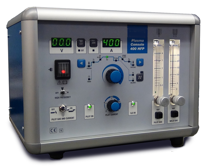
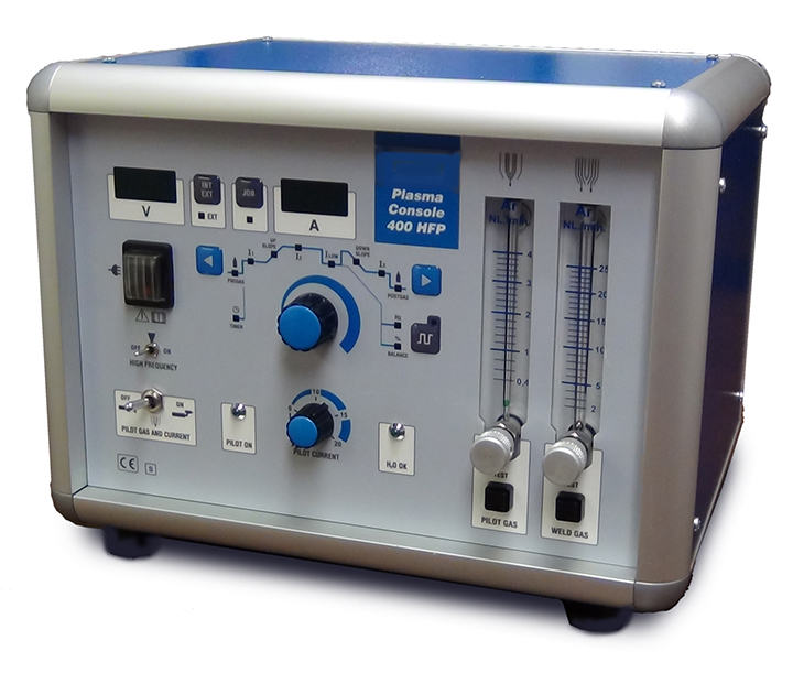
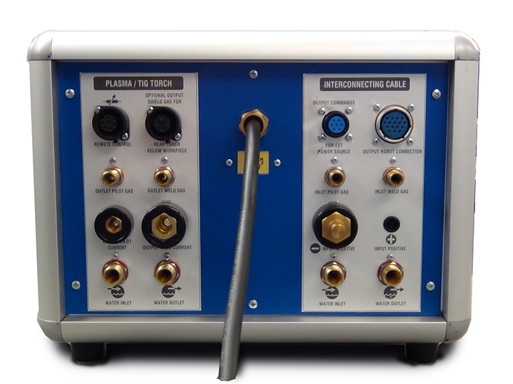
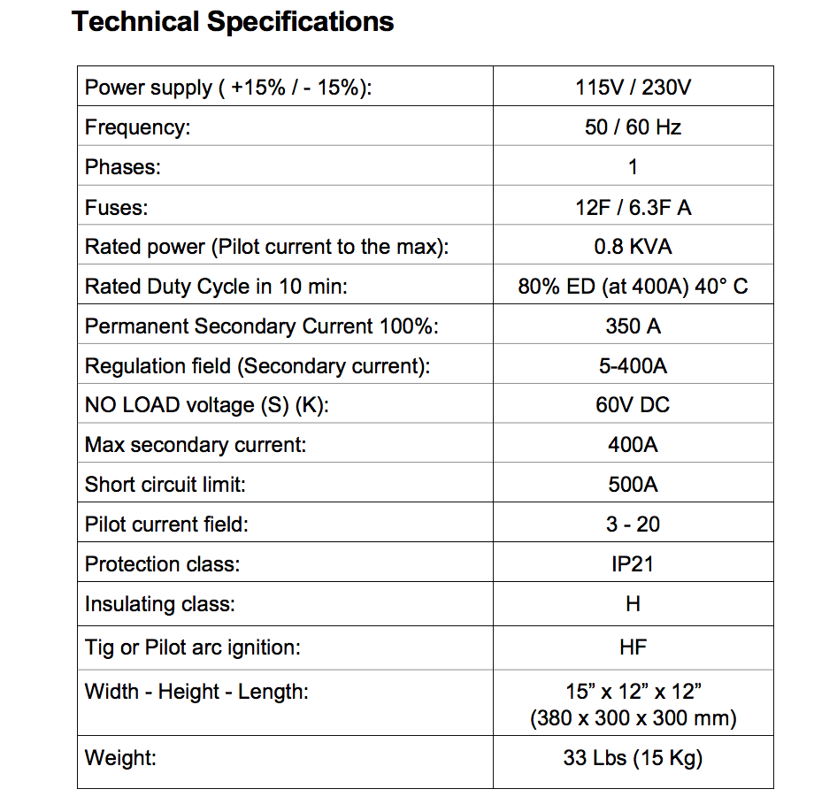
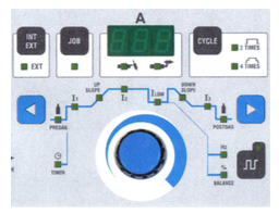
New Plasma Console 400 HFP

Plasma Console 400 HFP

Plasma OR TIG Welding

Add Plasma to Your Shop Using Your DC TIG Power Supply
Update Your Old Existing Console:
• Easy to Use
• Plasma & TIG Complete Cycle
• Built-In Memory for 10 Jobs 
• Pulsation
• Robot Connection
• ModBus Connection
• Small Compact Design 

We also offer water chillers and plasma torches to complete your plasma welding system.
We are here to help. Rely on:
Process Welding Systems, Inc.

Take Control With The Weld-Pro

ACCESSORY SCREEN


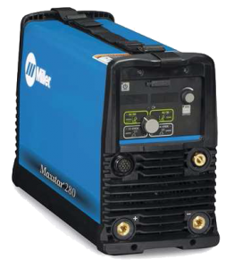
POWER SUPPLY


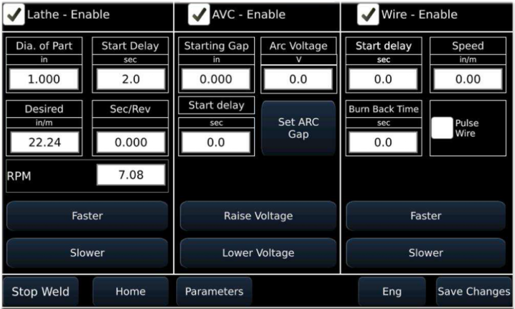
PARAMETERS CONTROLLED:

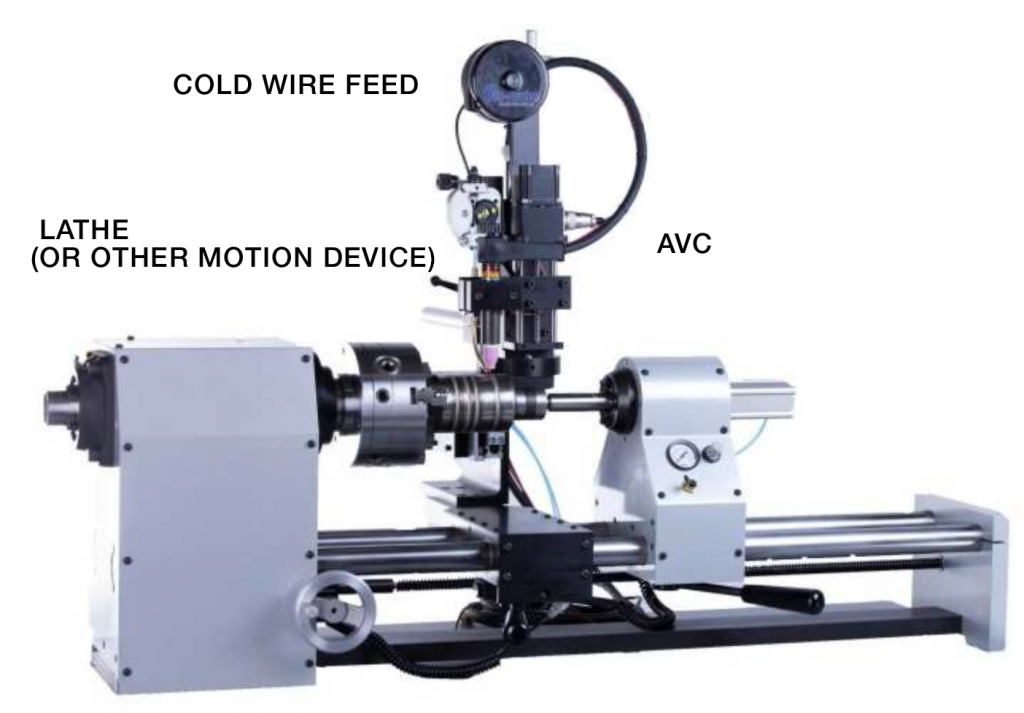
The Process Welding “WELD PRO” weld controller makes quick and easy work of changing from job to job with multiple devices. CAPABILITIES:

Control welding power supply, lathe or other motion device, AVC, wire feeder and aux gas from one location with either Modbus or
0 - 10V / analog signals!

• Pre-gas
• Initial Current
• Upslope
• Welding Current
• Pulsation Parameters
• Final Current
• Post-Gas
• Wire Start Delay
• Wire Speed
• Burnback Time
• Arc Gap Setting
• Arc Voltage
• AVC Start Delay
• Lathe Speed
• Lathe Start Delay

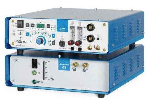
Dual Arc 82 Micro-Arc Power Supply

Process Welding Systems - Plasma and Tig Welding Solutions

DUAL PROCESS CAPABILITY FROM 0.1 TO 80.0 AMPS

MICRO PLASMA MICRO-TIG

SIMPLE PROGRAMMING AND PROGRAM STORAGE


————————————————————————

Pictured above: Dual Arc 82 Welding Power Supply on top, DA-WR Water cooler underneath (required for Plasma Welding Only) The system is 19.5” (50 cm) square
————————————————————————

The Most Capable Low Amperage Welding Systems Available

Micro -Tig System Capability:

  • •  Precision in Micro-TIG welding
  • •  Ultra low current capability (0.1 amp)
  • •  No arc wander at low amperages
  • •  Soft TIG arc start will not damage small or delicate parts
  • •  Reduced heat input thru built-in arc pulsation
  • •  Accurate, repeatable welds
  • •  Panel programmable start current, upslope, weld current, and final weld current levels
  • Manual and Automatic welding ability

————————————————————————

Micro—Plasma System Capability:

  • •  Micro-Plasma weld process ability offers all of the benefits of the plasma welding process (see page 2)
  • •  No Restriction to TIG or Plasma, it offers both!
  • •  Modular system can be purchased as a TIG system and later upgraded to include Plasma too
  • •  Short duration weld capability starting at 0.1 seconds
  • •  Built in computer control
  • •  Manual and Automatic welding ability

In either GTAW or PAW configuration, the Dual Arc 82 can be configured for manual or automatic welding and offers all connectivity required for automation of welding processes.

————————————————————————

TIG WELDING ADVANTAGES

  • •  Well-known and understood process
  • •  Readily available, low cost consumable parts
  • •  Excellent gas shielding for smaller parts
  • •  Electrode can be extended for improved weld joint access
  • •  “Soft” TIG arc can offer benefits for certain applications
  • •  More forgiving of part fit-up problems in certain applications————————————————————————

PLASMA WELDING ADVANTAGES

  • •  Protected electrode allows for more welds before electrode contamination
  • •  Arc gap distance not as critical as in TIG
  • •  “Gentle” arc transfer
  • •  Stable, stiffer arc reduces arc wander
  • •  No high-frequency arc starting noise
  • •  Extremely short duration welds possible for spot welding of wires, needles and micro components
  • •  Higher weld speeds in specific applications


Applications

And Many More

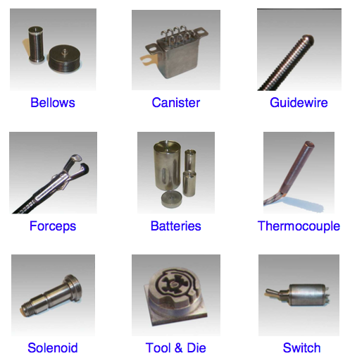
Valves, metal seals, diaphragms, pressure transducers, sensors, implant devices, relay cans capacitor cans, Micro switches, motors, electronic devices, enclosures, explosive detonators, airbag components, air seals, tube/ fitting assemblies, vacuum tubes, electrocautery tools, metal meshes, pacemakers, thermocouples, tube closure, surgical instruments, dental instruments, wires, aspiration needles, injection needles, surgical baskets, catheter metal capsules, guidewires, light bulb filaments, and more.

Read More

Standardization of Welding Procedures

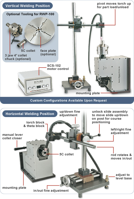
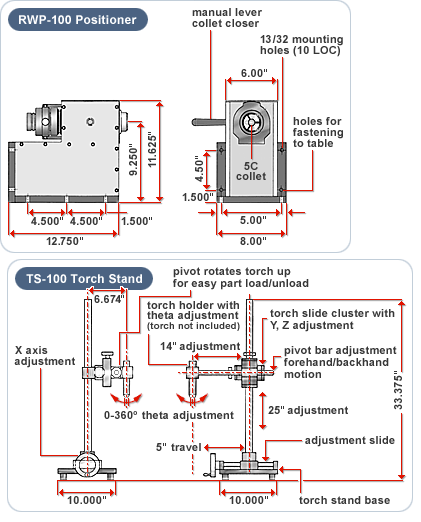
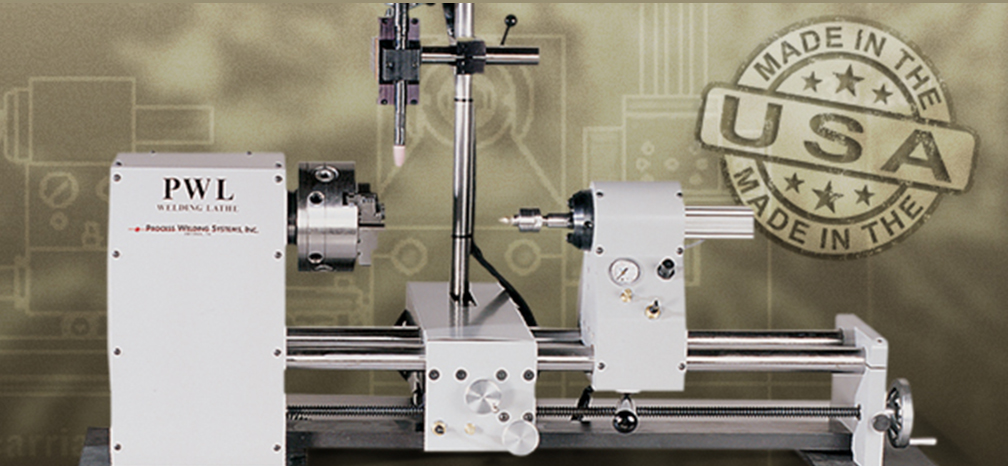
Weld Engineering has recently directed manufacturing engineering to adopt weld standardization into the production work cell. Weld standardization is a consistent and uniform approach to a given welding application. Standardization is divided into two critical components that include Process and Producibility. It is important to recognize that process control should remain independent of the theoretical approach utilized for a given welding application. The first step is to clone every element of each workstation in order to achieve the same process identity throughout production. The second component of standardization is Producibility. Producibility is simply the pursuit of a weld applications procedural limit. With each material there exists a weldability range in which a satisfactory weld can be produced. The candidate material or application is welded at a variety of speeds and parameters. Observations are documented as the window of Producibility is pushed to its maximum limit. This continues until some aspect of acceptance criteria is no longer satisfied. It is at this point that the low, middle, and upper control limits of the process are established. Standardization substantiates a company’s commitment to further product quality and establishes a basis for comparing quantity and quality. Qualification by similarity is one of the many benefits of standardization. Process Welding Systems Welding Positioner's are second to none. Call us today and ask about them and how best to improve the quality of your product production.

Welding Positioners


Costs of an Automated Welding System.

Basic parameters:

Operator and skilled welder salaries vary somewhat according to geographic locations. The basic assumptions used in the calculations below are as follows:
Work hours per year: 2000 (40 hours/week x  50 weeks/years)
Manual welder Costs
Average welder pay:     $16/hour (range from $14/hour - $18/hour)
Actual welder cost to employer:       $24/hour equals $48,000/year
(
1.5 X hourly rate for overhead, vacation, holidays, sick time, Social Security, unemployment taxes, insurance, etc.)

Operator Costs
Average operator pay:       $10/hour (range from $8/hour - $12/hour)
Actual cost to employer:  $15/hour equals 30,000/year
(1.5 X hourly rate for overhead)

The table below gives a simple example of calculations for return or investment based on equipment and labor costs alone. For a full analysis of actual costs the following must also be considered;

• Actual equipment cost • Labor rates • Production welding speeds possible • Supervisor cough • Personal management • Quality control costs • Reject and scrap cost • Customer relations •

Number of systems required for the call output.

8x

4x

1x

Individual system cost
Total equipment system investment

$5,000
$40,000

$32,000
$128,000

$200,000
$200,000

Individual welder cost/year
Individual operator cost/year
Labor cost/year for equal volume of output.
(One 8 hour shift)

$48,000


$384,000


$30,000

$120,000


$30,000

$120,000

Labor and equipment cost for a 12 month
period with one eight hour shift

$424,000

$248,000

$230,000

Labor and equipment cost for a 12 month
period with one eight hour shift

$808,000

$368,000

$260,000

Carbon Steel – Welding


Carbon steel is steel where the main interstitial alloying constituent is carbon in the range of 0.12-2.0%. The American Iron and Steel Institute (AISI) defines carbon steel as the following: "Steel is considered to be carbon steel when no minimum content is specified or required for chromiumcobaltmolybdenumnickelniobiumtitaniumtungstenvanadium or zirconium, or any other element to be added to obtain a desired alloying effect; when the specified minimum for copper does not exceed 0.40 percent; or when the maximum content specified for any of the following elements does not exceed the percentages noted: manganese 1.65, silicon 0.60, copper 0.60."


 Mild and low carbon steel

Mild steel, also called plain-carbon steel, is the most common form of steel because its price is relatively low while it provides material properties that are acceptable for many applications, more so than iron. Low carbon steel contains approximately 0.05–0.3% carbon[1] and mild steel contains 0.3–0.6%[1] carbon; making it malleable and ductile. Mild steel has a relatively low tensile strength, but it is cheap and malleable; surface hardness can be increased through carburizing.[3]

Higher carbon steels

Carbon steels which can successfully undergo heat-treatment have a carbon content in the range of 0.30–1.70% by weight. Trace impurities of various other elements can have a significant effect on the quality of the resulting steel. Trace amounts of sulfur in particular make the steel red-short, that is, brittle and crumbly at working temperatures. Low alloy carbon steel, such as A36 grade, contains about 0.05% sulfur and melts around 1426–1538 °C (2599–2800 °F).[8] Manganese is often added to improve the hardenability of low carbon steels. These additions turn the material into a low alloy steel by some definitions, but AISI's definition of carbon steel allows up to 1.65% manganese by weight.


Medium carbon steel

Approximately 0.30–0.59% carbon content.[1] Balances ductility and strength and has good wear resistance; used for large parts, forging and automotive components.[9]

High carbon steel

Approximately 0.6–0.99% carbon content.[1] Very strong, used for springs and high-strength wires.[10]

Ultra-high carbon steel

Approximately 1.0–2.0% carbon content.[1] Steels that can be tempered to great hardness. Used for special purposes like (non-industrial-purpose) knives, axles or punches. Most steels with more than 1.2% carbon content are made using powder metallurgy. Note that steel with a carbon content above 2.0% is considered cast iron.

Heat treatment

The purpose of heat treating carbon steel is to change the mechanical properties of steel, usually ductility, hardness, yield strength, or impact resistance. Note that the electrical and thermal conductivity are only slightly altered. As with most strengthening techniques for steel, Young's modulus (elasticity) is unaffected. All treatments of steel trade ductility for increased strength and vise versa. Iron has a higher solubility for carbon in the austenite phase; therefore all heat treatments, except spheroidizing and process annealing, start by heating the steel to a temperature at which the austenitic phase can exist. The steel is then quenched (heat drawn out) at a high rate causing cementite to precipitate and finally the remaining pure iron to solidify. The rate at which the steel is cooled through the eutectoid temperature affects the rate at which carbon diffuses out of austenite and forms cementite. Generally speaking, cooling swiftly will leave iron carbide finely dispersed and produce a fine grained pearlite (until the martensite critical temperature is reached) and cooling slowly will give a coarser pearlite. Cooling a hypoeutectoid steel (less than 0.77 wt% C) results in a lamellar-pearlitic structure of iron carbide layers with _-ferrite (pure iron) between. If it is hypereutectoid steel (more than 0.77 wt% C) then the structure is full pearlite with small grains (larger than the pearlite lamella) of cementite scattered throughout. The relative amounts of constituents are found using the lever rule. The following is a list of the types of heat treatments possible:

There Are Differences in Welding

Difference Between MIG and TIG Welding

The Basic difference between MIG and TIG welding is that one uses consumable wire electrode (MIG) and other (TIG) uses non-consumable tungsten electrode. In MIG welding process, electric arc is produced between a consumable wire electrodes and workpiece metals. And in TIG welding process, electric arc is produced between a non-consumable tungsten electrode and workpiece metals. The heat generated by the arc is used to melt the metals and forms weld. Here we will discuss all the major differences among MIG and TIG Welding.
Difference Between MIG and TIG Welding

Difference Between MIG and TIG Welding

Here we have learnt all the major difference between MIG and TIG welding. If you have any questions regarding this article than comment us at Process Welding Systems.

S.no
MIG Welding
TIG welding
1.
MIG stands for Metal Inert Gas Welding. It is also known as Gas Metal Arc Welding (GMAW), Metal Active Gas Welding (MAG).

TIG stands for Tungsten Inert Gas Welding. It is also known as Gas Tungsten Arc Welding (GTAW).
2.
It is a welding process in which electric arc is formed in between a consumable wire Electrode and workpiece metal(s).

It is a process in which an electric arc is formed in between a non-consumable tungsten electrode and workpiece metal(s)
3.
The type of electrode used is consumable wire electrodes.

The type of electrode used is non-consumable tungsten electrode.
4.
Most commonly it uses constant voltage, direct current power source for the welding. It can also use constant current system and alternating current.

It uses constant current welding power supply for the welding.
5.
The materials which it can weld are aluminum, non-ferrous materials and steels.

It is most commonly used to weld stainless steels and non-ferrous metals like aluminum, magnesium and copper alloys.
6.
High skilled operator is not required to perform MIG welding process.

High skilled operator is required to perform TIG welding process.
7.
It has high weld deposition rate.

It has low weld deposition rate as compared with MIG welding.
8.
No filler metal is required. The feed electrode wire melts and acts as filler metal.

It may require filler metal from outside in some cases if needed.
9.
It can weld thick metal sheets up to 40 mm.

It can weld thin metal sheets up to 5 mm.
10.
It produces less quality of weld as compared with TIG.

It produces high quality of weld because it affords greater control over weld area.
11.
It uses continuous wire feed.

It does not uses continuous wire feed.
12.
The equipment used in MIG welding process is a welding gun, a welding power supply, a feed wire unit, a welding electrode wire and a shielding gas supply.

The equipment used in TIG welding process is welding torch, non-consumable tungsten electrode, a constant-current welding power supply and a shielding gas source.
13.
It is a faster welding process.

It is a slower welding process.
14.
In this welding process, the use of filler metal is compulsory.

But in this welding process the filler metals may or may not be used. There is no compulsion of using filler metals, it is used when required.
15.
 It cannot work in any position.
It can be worked in any position.